
The RI8611A Cassini V93K CTH Infrastructure (referred to as "Cassini Infrastructure") can be installed and removed with the MZYB336A Cart for Cassini V93K CTH Infrastructure (referred to as "Cart". The methods for attaching and removing the Cassini Infrastructure from the Advantest V93000 SoC Tester (referred to as "V93K Head") are detailed in the following text. These instructions assumes the Cassini Infrastructure has not yet been setup with TIMs installed in their required T-Locations and a Fixture attached. TIMs were designed to be inserted and removed quickly to support the reconfigurable nature of Cassini’s modular test head as well as service requirement needs. The universal test head slots and standard TIMs allow Cassini to be reconfigured in support of different applications, site, and/or customer requirements. Included in the following text are instructions for inserting and removing standard TIMs on the Cassini test head.
Tools Needed:
- Torx T20 or T25 driver
- 9/16-in Wrench*
- Zip Ties for 48V Power Supply*
- Allen 4mm Ball end T-Handle wrench*
- Air Bubble Level or Smartphone Level Application*
*Optional to make adjustments
To Attach a RI8611A Cassini V93K CTH Infrastructure to Advantest V93000 SoC Tester:
- Position the MZYB336A Cart for Cassini V93K CTH Infrastructure near the Advantest V93000 head and position the head to prepare for docking.
- Inspect the Infrastructure and all connectors to the Advantest V93000 head for any signs damage. Look closely at pins and pin housings, as pins can sometimes get pushed down to far into the connector. Look for cleanliness and security of the Infrastructure and all switches & connectors. When cleaning the connectors, use compressed air to clean the connectors on the Infrastructure. Use an all purpose cleaner to clean the system. Its best to spray the cleaner directly onto a cloth to wipe down the Infrastructure vs. spraying the cleaner on the system.
- On the Advantest V93000 head, lock the floating base ring to minimize sagging due to the forward weight. (See Figure 2) Use a Torx T20 or T25 driver to loosen and move the locking tabs into position so that they are securing the ring. As illustrated in Figure 2a, if the tabs are in the unlocked position (red "X"), then loosen the screws and slide inward, then tighten to make them look like the green check mark.
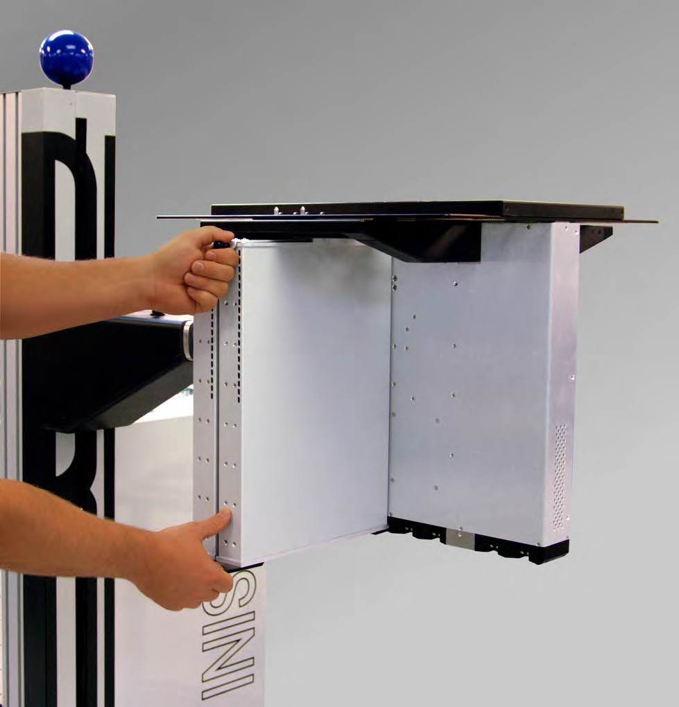
- Position on the Advantest V93000 docking area by lining up the visible rollers of Infrastructure to slots on the back of the like the green lines show in Figure 3. Lock the wheels to prevent the Cart from rolling.
- (Optional) Use the Advantest V93000 remote HARD DOCK button to activate the pneumatic rollers once the infrastructure is securely on the Advantest V93000 shown in Figure 1.
- Attach the external 48V Supply to the Advantest V93000 handle. Use zip ties to attach the 48v power supply brick to the handle of the Advantest V93000 as shown by blue arrows in Figure 4.
- Attach the 6-Pin Molex Connector (see Figure 5a and 5b) to the Cassini Infrastructure cable.
- Attach the AC C-13 cord via an optional switchable power strip and/or Y-Cable to the IEC320 C-14 plug located on the resource ring on the back of the Advantest V93000, see the yellow arrow in Figure 5c or facility provided AC power. This will power the infrastructure, it is safe to attach and remove the TIMs and the Fixture while powered On.
- (Optional) Plastic bars rest on the pucks of the Advantest V93000 have been adjusted at the factory so that the head will be level when resting on them. Use a smart phone level application to confirm. If the infrastructure is not level, then use an Allen 4mm ball end T-Handle wrench to loosen the 4 cap head screws (on each side purple arrows.) Use an assistant to lift the infrastructure with the screws loose while observing the level resting on the top plate. Once level, then the assistant should tighten all of the screws as shown in Figure 6.
- Follow the steps below to Install TIMs in their required locations. Refer to the T-Location labels near each TIMs Serial Number label or Tester Configuration diagram in the Diag Kit Case.
- Connect the USB RIFL "Command and Control" cable from the RI8611A Infrastructure to an available USB port on the Advantest V93000 system controller.
- Continue with Advantest SmartTest8 setup instructions on the Advantest V93000 system controller.
Before handling Test Instrument Modules (TIMs), always:
• Exercise proper ESD procedures with the Cassini test system, fixtures, and TIMs.
• Remove any fixtures or diagnostic/calibration plates from the test head to prevent damage to blind-mate interfaces.
• If the rTalk Saturn software is running, perform a System Check to update the system configuration before handling the TIM(s).
• Inspect the TIM(s) to insure that no damage has occurred to the chassis or blind-mate interface and check that air exhaust channels are free of debris. As well, verify that mechanical components such as the bottom and top latch releases and locks are operating correctly. Contact [email protected] with the TIMs serial number to request an RMA for repair or calibration.
To install a TIM:
- Hold the TIM using the top and bottom latch releases in the unlocked position with the blind-mate interface facing up as shown in Figure 10.
- Bring the TIM up to the test head from underneath, using the alignment pins and blind-mate interface to guide the TIM into the test head slot.
- When the alignment pins are visibly through the test head, the TIM’s top-latch should be resting against the underneath of the test head and the clasps of the top latch should extend past the top of the test head.
- Continuing to hold the TIM in this position, insure the bottom latch insert is aligned with the slot’s associated detent receiving port.
- Release the bottom latch handle to engage the bottom lock and continue to hold the bottom of the TIM up against the bottom side of the test head. The engaged bottom latch will prevent the TIM from accidental drops while the top latch is not engaged.
- Engage the top latch by pressing the lever arm down the against the side of the TIM.
- Inspect the top latch clasps to insure they have engaged the top of the test head and that the TIM is securely in place.
- Perform a software System Check to activate the TIM. This step can be skipped if the system is OFF.
To remove a TIM:
- Grasp the top-latch release and pull the top-latch handle upwards and away from the side of the TIM. This will release the TIM’s top-latch clasps from the test head and the TIM will rest on the engaged bottom latch approximately ~6mm (0.25in) below the test head.
- The distance between the TIMs top latch and the test head plate will disengage the RIFL block from the 48V instrument supply and the communication bus.
- Verify that instrument power has been removed from the TIM by performing a software System Check to confirm the TIM instruments are no longer in the Tester Configuration or Equipment Pool list. This can also be confirmed by checking that the fan on the bottom of the TIM is no longer running.
- Holding the top latch release handle firmly, pull the bottom latch release tab directly away from the center of the test head in a motion parallel to the test head plate to release the TIM completely from the test head.
- Move the TIM away from the test head in downward motion to prevent contacting the TIM slot RIFL pins underneath the test head and adjacent TIMs. Always store removed or inactive TIMs in a ESD safe, temperature controlled environment.
To Remove a RI8611A Cassini V93K CTH Infrastructure from Advantest V93000 SoC Tester:
- Disconnect the USB Command and Control cable from the RI8611A Infrastructure from the Advantest V93000 controller.
- Position the MZYB336A Cart for Cassini V93K CTH Infrastructure under the RI8611A Cassini V93K CTH Infrastructure and lock the caster to prevent from movement. Use the (optional) Advantest V93000 remote to move the test head DOWN onto the cart. Otherwise prepare two people to hold the RI8611A Cassini V93K CTH Infrastructure before undocking (next step).
- Use the Advantest V93000 remote HARD UNDOCK button to activate the pneumatic rollers to release the RI8611A Infrastructure shown in Figure 1.
- Use the Advantest AC Power Switch or external Power Strip Power Switch to the OFF position.
- Disconnect the AC Power cord from the 48V Power Supply or AC plug located on the resource ring on the back of the Advantest V93000, see the yellow arrow in Figure 5c.
- Secure the Cassini Infrastructure by having two people move it to the Cart.
- Move the Cart with Infrastructure away from the Advantest test head. When not being moved, lock the casters to prevent from moving.
- (Optional) On the Advantest V93000 head remote control, unlock the floating base ring. Use a Torx T20 or T25 driver to loosen and move the locking tabs into position so that they are no longer securing the ring as shown in "red X" in Figure 2a.
Figure 1: Advantest V93000 Head remote control
Figure 2: Location of the V93000 Floating Base Ring
Figure 2a: Locking the V93000 Floating Base Ring (Red X is Unlocked, Green Check is locked)
Figure 2b: Locking the V93000 Floating Base Ring Photo
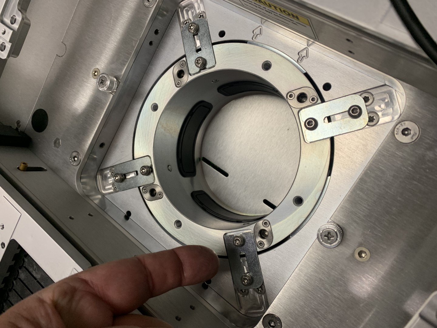
Figure 3: Align and Attach Infrastructure
Figure 4: Power Supply mounted to head
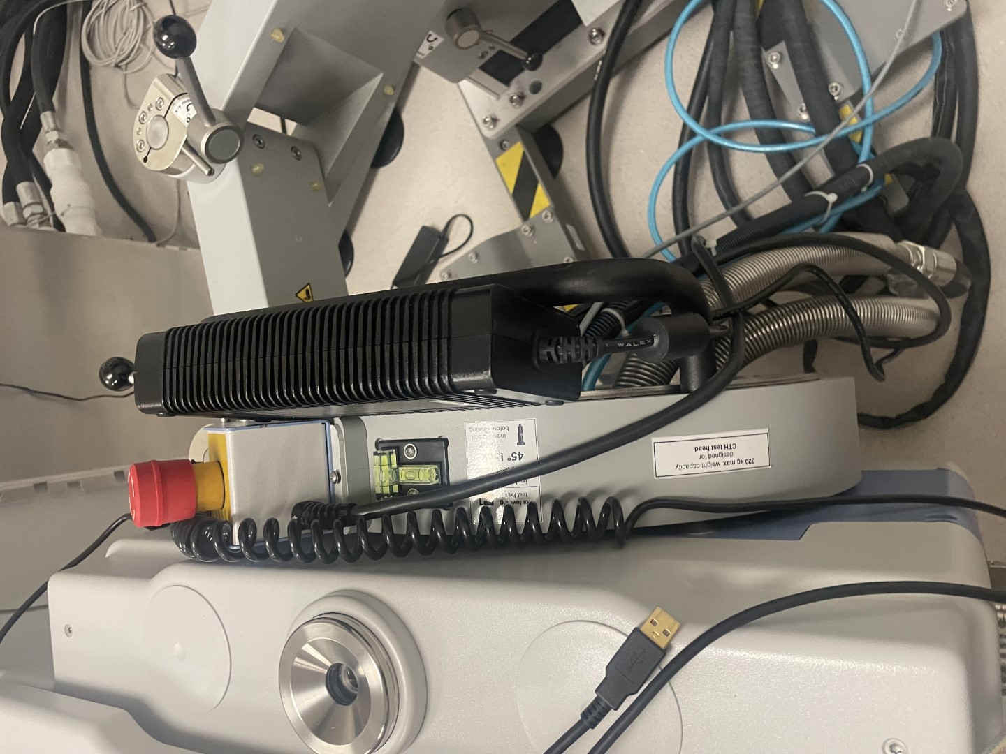
Figure 4b: Power Supply mounted to head, and USB Command and Control cable alternate angle
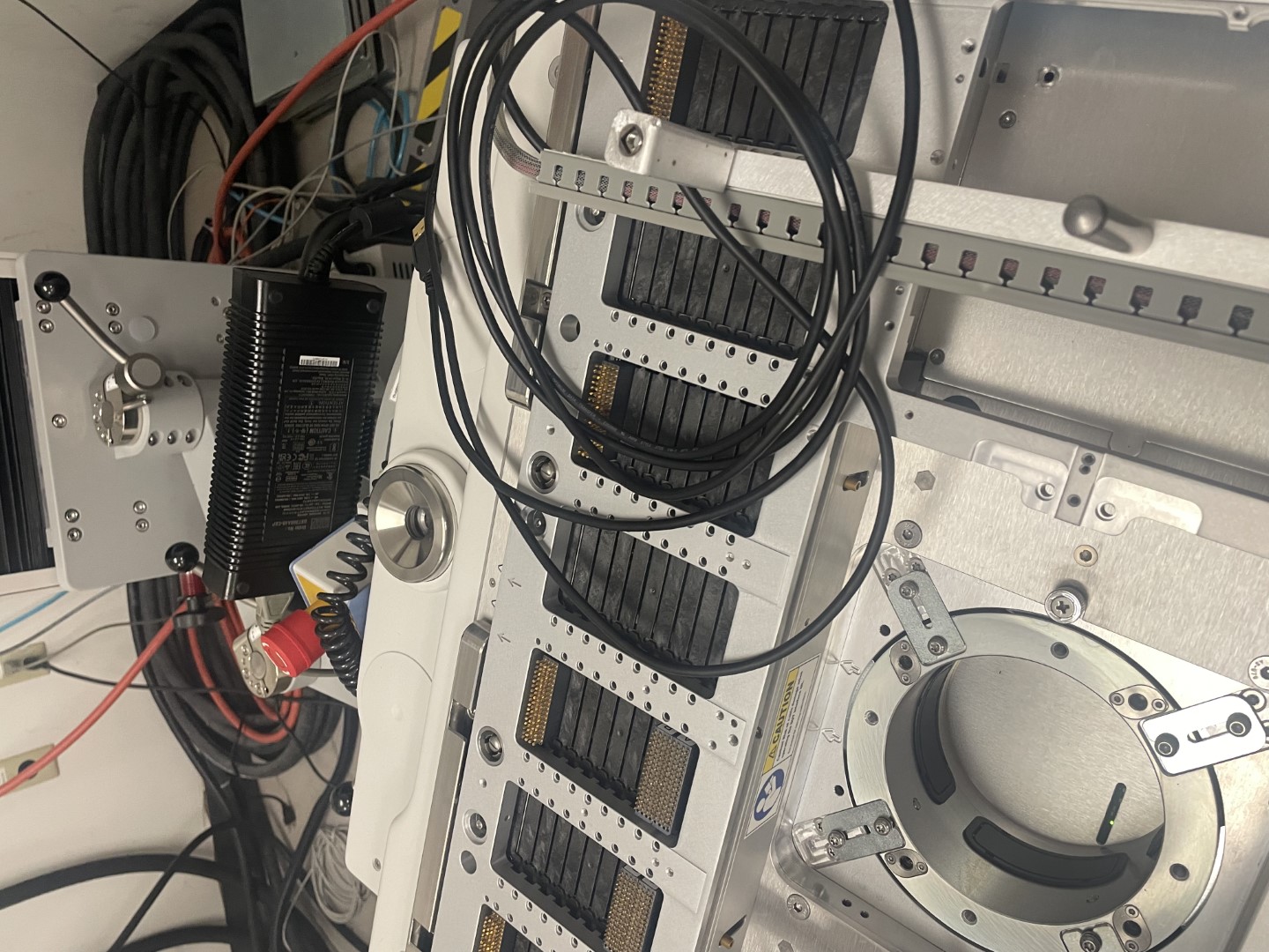
Figure 5a: DC Connector to 360W AC-DC Adaptor
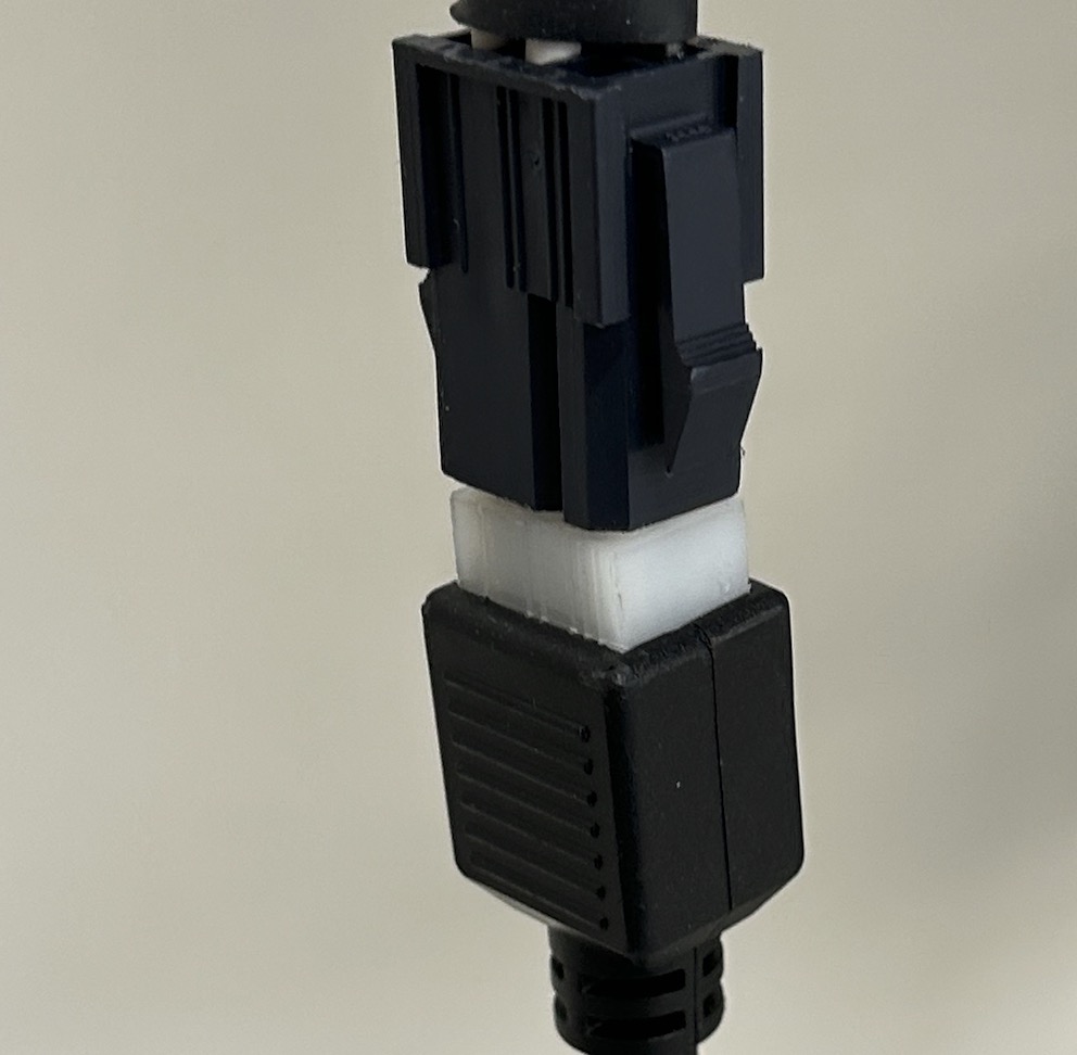
Figure 5b: Six-Pin Molex Connector Diagram and Pinout
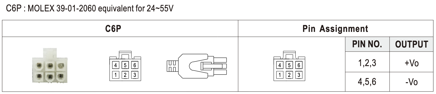
Figure 5c: AC Power Plug for 48V Power Supply
Figure 5d: AC Y Splitter and C13 AC Switch
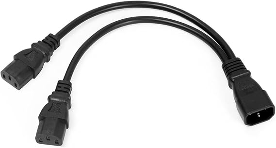
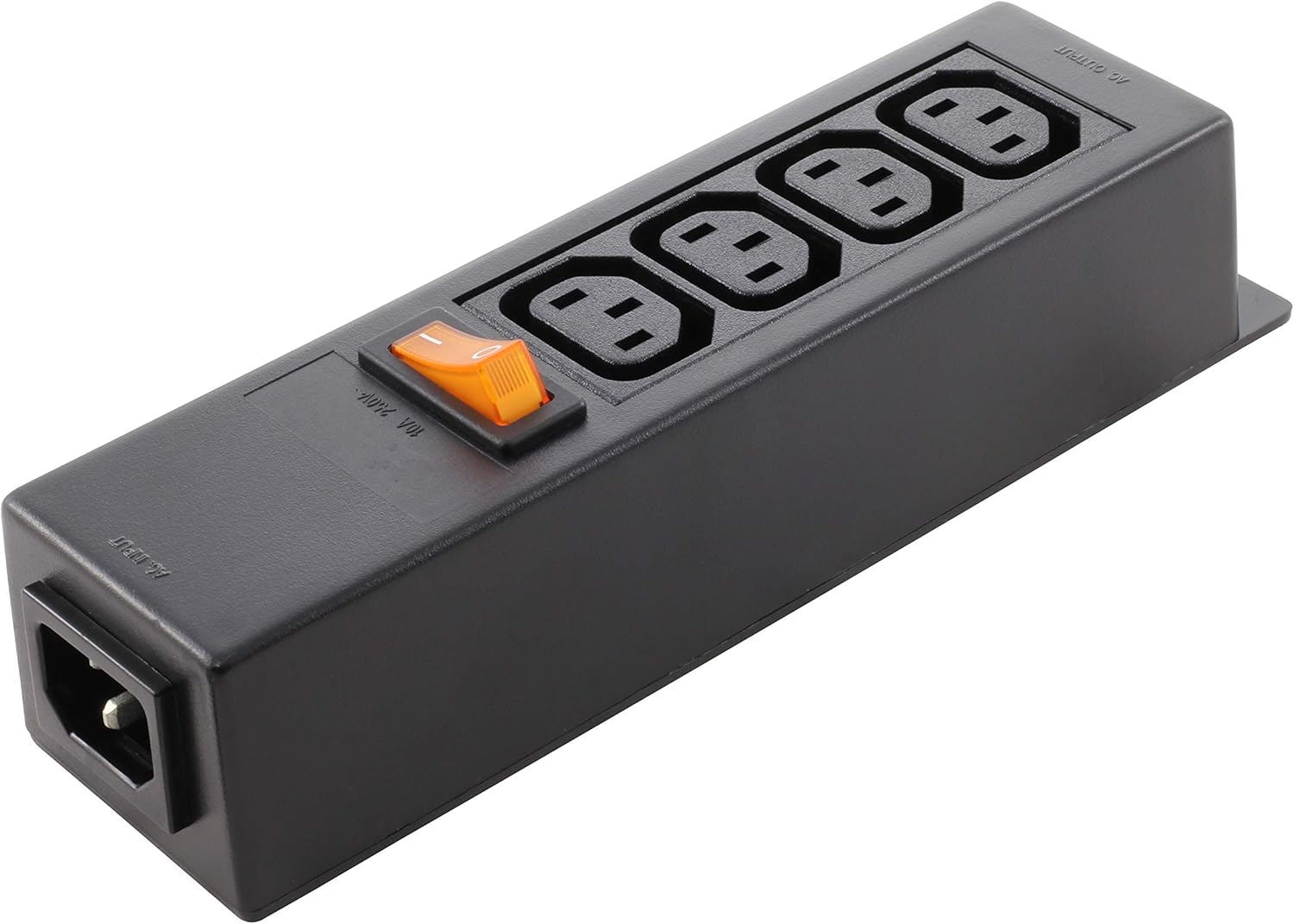
Figure 6: Alignment Adjustments
Figure 7: To Adjust Advantest V93000 Manipulator Arm
Figure 8: Cart with V93K CTH Infrastructure attached to Head
Figure 9: Cart with Cassini V93K CTH Infrastructure
Figure 10: Adding a TIM to Cassini Infrastructure