Follow these instructions ONLY when directed by Roos Instruments Support to repair a problem with failing DevicePower, StaticDigital or PowerVI instrument. Replacement internal module must be available.
- To replace a failed Testhead module:
- Turn off the testhead power.
- Remove testhead bottom cover.
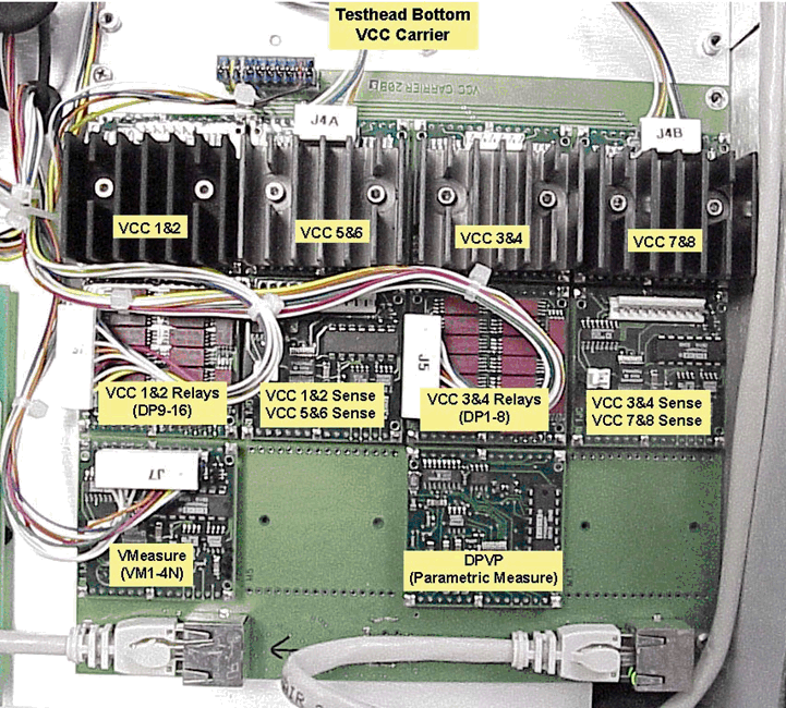
- Find associated bad VCC boards from Figure 1 below.
- Replace the damaged module.
For Example: VCC pcb Y0000PB1, If the failed VCC is 1/2 or 3/4 also replace the VCC Relay pcb Y0001RB1. - Confirm that the boards are in the proper orientation and are pushed all the way into their sockets. If it is VCC 5/6 or 7/8 make sure its cable is plugged back into the its pcb.
- Replace the testhead bottom cover.
- Turn on testhead power.
- Install calibration Fixture.
- Start the RI System Software.
- Make a backup copy of the tester.
- From the calibration window run the Cal plans which have the failed VCC included in the plans name.
- If you encounter any problems, Save the tester and send us a copy of the tester.sys file with the new cal data in it.
- Test with a production part to verify operation.
Figure 1: RI7100A Testhead Bottom VCC Carrier

Reference Figure 1 PDF
![]() RI7100A Testhead Bottom VCC modules.pdf
RI7100A Testhead Bottom VCC modules.pdf

