
These instructions are for systems that not have the ability to calibrate E-band TIMs due to an outdated (as of June 2024) Cal Fixture(s) and Cal List. This corrects for a symptom where the Receiver Voltage measurements are offset values when using different If Bw values for different ports when we are expecting the same value.
First follow the procedure to "To Inspect Testhead77 Cal Values" then, if the cal data is not valid or is the default value, proceed with "To Manually Calibrate Receiver Filters for Testhead77 Instrument".
Fortunately, the E-band TIM error is constant vs. frequency, so we don't need a full frequency response cal. What follows are instructions to manually enter calibration factors to correct for the 7 kHz and 30 kHz bandwidth error. We will be entering the same value into 3 cal factors. They are the cal offsets for a1 (what comes out of port 1), b1 (what goes into port 1), and b2 (what goes into b2) when the receiver is in the 7 kHz or 30 kHz IF bandwidth.
Requirements
RiInstrumentDef with ri.sys.Name=Ri8580A ri.sys.CreationDate = 2024-07-10 or later. (See Figure 5)
Cassini app launched from a Short Cut with Patch 343.15 Ri8580B 50 -70Ghz Test Set (See Figure 6)
To Inspect Testhead77 Cal Values:
- From the Cassini window Choose System > Tester to open the configuration window. Left click on Testhead77, then choose Calibration > Inspect from the right Mouse Button Click (RMBC) menu to open the Inspecting Cal Table window.
- Scroll down until you find filterGainOffsetRf1a. Double-click it to open the Inspecting RiFrVsReal window.
- Valid Cal data would have multiple points or if only 2 points, one at 45000 MHz and the other at 75000 MHz with a value other than 1 (linear ratio). If there are only two points AND the value is 1, then follow the steps below "To Manually Calibrate Receiver Filters for Testhead77 Instrument".
- From the Cassini app, choose Options > Show Patches... and scroll down to identify GF10RC2A.343-15 (or greater) then choose Cancel to close the window. If the patch is not included, close this version of Cassini and launch from the latest Dev version.
- From the Guru Apps button, choose Guru Browser, then select RiInstrumentDef from the pulldown menu under ri.sys.ObjClass and scroll down to view ri.sys.Name=Ri8580A ri.sys.CreationDate = 2024-07-10 or later. (See Figure 5). Contact RI support ([email protected]) to get a copy of this.
To Manually Calibrate Receiver Filters for Testhead77 Instrument:.
- First, determine the magnitude of the error. Whatever steps were followed to identify an error, do it again. For example, open an E-band test plan with a thru path and set a breakpoint, choose Control to open a controller window and then Receiver > control.
Measure a valid signal with 30 kHz BW by choosing If Bw > 30KHz and left clicking on the VOLTAGE DBM button to update the display and write the value down as variable "a". Then choose If Bw > 30KHz button and left clicking on the VOLTAGE DBM button to update the display and write the value down as variable "b". Compute the db ratio between 30 kHz and 200 kHz values by dividing the larger value over the smaller one i.e. ("a/b" when "a" is larger). For polarity of the offset, if the 30 kHz path measures more power than the 200 kHz path, the error that you will need to enter is positive. If 30 kHz measures less than 200 kHz, enter the error as a negative number.
The same value will be entered into 3 cal factors that are the cal offsets for a1 (what comes out of port 1), b1 (what goes into port 1), and b2 (what goes into b2) when the receiver is in the 7 kHz or 30 kHz IF bandwidth. - Choose System > Tester to open the configuration window. Left click on Testhead77, then choose Calibration > Inspect from the right Mouse Button Click (RMBC) menu to open the Inspecting Cal Table window. (See Figure 1)
- Scroll down until you find filterGainOffsetRf1a. Double-click it to open the Inspecting RiFrVsReal window. Because this piece of cal data is reset, there are only 2 points, one at 45000 MHz and the other at 75000 MHz.
- Choose the first point labeled 1. (See Figure 2)
- In the right panel, choose RiRealD. This will open the entry panel titled real.
- Choose the lin button to switch to log and the value changes from 1 (linear ratio of 1) to 0 (0 dB). The cal factor is in voltage ratio, but we want to enter it in dB. (See Figure 3)
- Now click in the text entry window, backspace over the '0', and enter the error value you determined in step 1.
- Choose OK and the RiRealD number is now displayed as a linear voltage ratio.
- Choose the 2nd point labeled 2, and repeat steps 5-8. At this point, you should have the same voltage ratio in both cal points. This means that the tester will apply the same correction at all frequencies.
- Repeat steps 3 thru 9 for the following cal factors:
filterGainOffsetRf1b
filterGainOffsetRf2b - Close the Inspecting Cal Table window by clicking the X in the upper right corner.
- From the Configuration window, Testhead77 should still be highlighted, choose Calibration > Save from the right mouse button menu to save the Instrument cal data to Guru.
- Using whatever method you used in step 1, confirm that the 200 kHz and 30 kHz bandwidths now measure the same number.
Figure 1: Testhead77 > Calibration > Inspect
Figure 2: Calibration Inspect filterGainOffsetRf1a
Figure 3: Edit Value at 60 GHz
Figure 4: Calibration Testplan (requires updated Cal List)
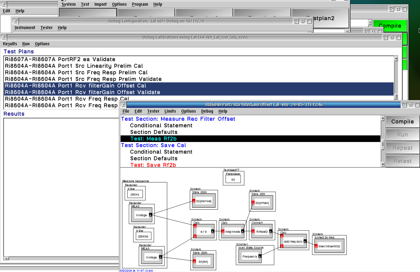
Figure 5: RiInstrumentDef for Ri8580B
Figure 6: Patch 343.15 for Ri8580B