
This document provides you with a step by step process for unpacking a RI8611A Cassini V93K CTH Infrastructure from boxes to prepare for attaching to the Advantest V93000 SoC Tester.
Prepare the site for installation:
 Site Preparation Guidelines for RI8611A Cassini V93K Infrastructure
- Cassini V93K CTH Infrastructure System Setup Check List
- Cassini V93K CTH Infrastructure Attach and Remove with Cart
Tools Needed: (Included in shipment)
- Torx T20 or T25 Screwdriver
- 9/16-in Wrench
- Zip Ties for 48V Power Supply
- Allen 4mm Ball end T-handle wrench
- #1 Phillips Head Screwdriver
Unpack the Cassini V93K CTH Infrastructure:
- Unpack the boxes starting with Box 1 to access the packing list and then proceed to unpack the Cart (~120x76x76cm) and then Infrastructure (~120x76x76cm), then TIM Boxes (64x48x15 cm), Fixture Box and any additional accessory boxes.
IMPORTANT: DO NOT DISCARD ANY PACKING MATERIAL. Retain all boxes to return items back to the factory for calibration, upgrades or service. - Remove the Cart from its box, carefully removing filler material and boxes. Lock the four cart wheels to prepare for placing the RI8611A Infrastructure (see Figure 3). Only open filler boxes marked with "hardware enclosed" and leave the other boxes closed.
- Carefully remove "hardware" and filler boxes to access the RI8611A Infrastructure. Retain all HARDWARE boxes with Hardware. The Infrastructure is shipped on the side with the heavy side down, remove the protective bag and place it on the Cart. This requires two people to lift due to size and its center of gravity where the weight is located. (See Figure 2)
Note: Spare equipment may be included that will be hand carried back with the RI technician after installation. This spare equipment is intended to allow for rapid installation and replacement of any components damaged during shipment. - Inspect the Infrastructure and all connectors to the Advantest V93000 head for any signs damage. Look closely at pins and pin housings. Pins can sometimes get pushed down to far into the connector. Look for cleanliness and security of the Infrastructure and all switches & connectors. When cleaning the connectors, use compressed air to clean the connectors on the Infrastructure. Use an all purpose cleaner to clean the system. Its best to spray the cleaner directly onto a cloth to wipe down the Infrastructure vs. spraying the cleaner on the system.
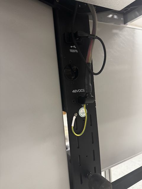
- Remove the DC cables from the protective bag as shown in Figure 5. Connect the 6-Pin power plug to the 48VDC25A plug and unscrew then connect green/yellow ground wire to the ground screw using a Philips screwdriver. (See Figures 6 and 7)
- Unpack the TIM and Fixture boxes and follow the instructions to latch the TIMs and Fixture. The TIMs and Fixture should be unlatched and removed after moving the system close to the Advantest V93000 CTH Testhead. Follow the steps To install a TIM in the Cassini V93K CTH Infrastructure Attach and Remove with Cart instructions.
Note: Compare the Serial Numbers with the items identified on the Commercial Invoice and report any discrepancies to RI support([email protected]) as soon as possible. - Move the Cart and Hardware Boxes to the V93K and proceed to complete the Cassini V93K CTH Infrastructure Attach and Remove with Cart
Figure 1: TIM Boxes, Fixture Case and Diag Kit Case
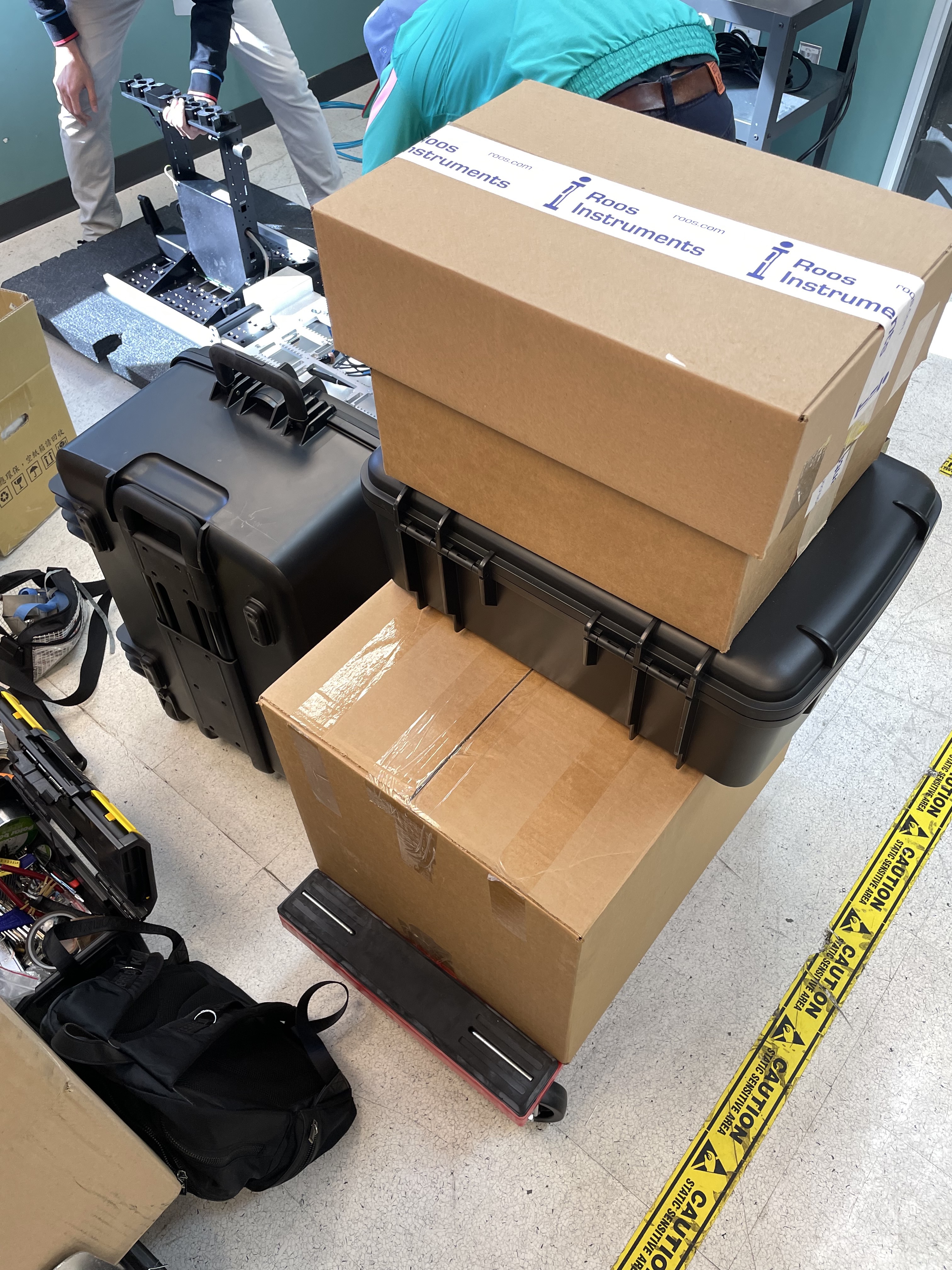
Figure 2: RI8611A Advantest V93000 Cassini Infrastructure Assembly
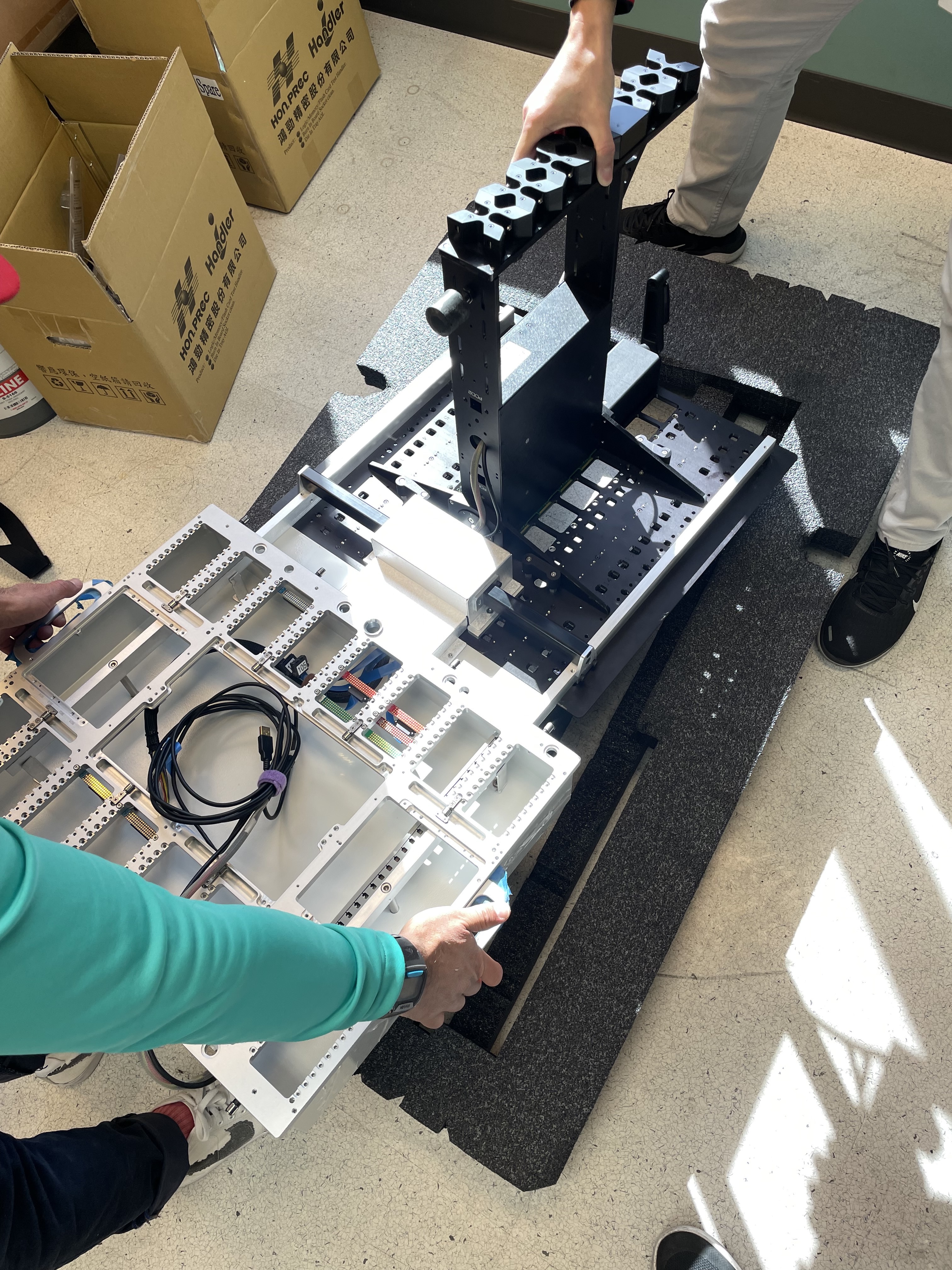
Figure 3: Locking Wheels
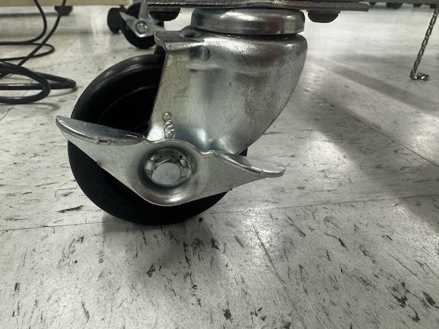
Figure 4: Cart with Cassini V93K CTH Infrastructure
Figure 5: DC and Ground Secured for Transport
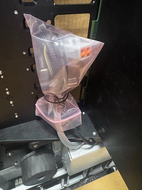
Figure 6: Infrastructure DC Plug and Ground point Before Connecting
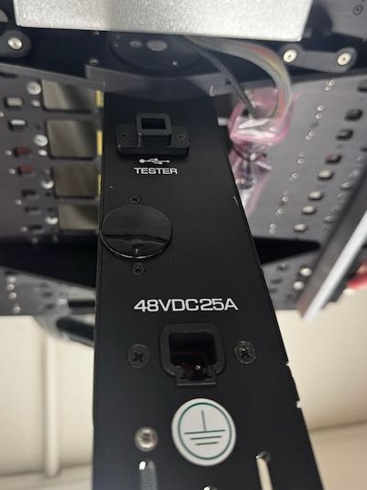
Figure 7: DC and Ground After Connecting