

Due to supply constraints, the RI8567 TIM has been updated to use a different vendor for the RF switches inside the TIM. These new switches have a different 50 Ω match characteristic.
- Applies to RI8567 RfMeasure TIMs shipped after May 2024. (version B4 and later, First 3 Characters of Serial Number are "RPV" and higher)
- See the Table of RI8567B TIMs for affected serial numbers.
- This document provides best‑practice configuration steps to maintain consistent match performance across hardware revisions.
Symptom
- Mismatch ripple appears in calibrated Fixture paths, where power seems to add or subtract at different frequencies.
- This effect is repeatable and predictable, so final measurements remain valid. Calibration compensates for both source and receiver paths.
- Fixture calibration is hardware‑generation dependent: (see Identifying TIM Hardware Revision)
- B3 and earlier: smoother calibration curves
- B4 and later: ripple visible (see Figure 1) unless best-match configuration is used
- Following the best‑match procedure aligns calibration data across TIM hardware generations.
Recommendations
- Share this document with engineers comparing Fixture calibration data between B3‑and‑earlier and B4‑and‑later TIMs.
- Avoid swapping TIMs between hardware generations. If swapping is required, perform a full Fixture calibration.
- No software changes are needed, but document and communicate the expected calibration differences (see Figure 1).
- If source match issues are identified, follow the procedure “Update Testplans for Best Match S‑Parameter Measurements”.
- Always update both Fixture Calibration Test Plans and Device Test Plans to use the same switched paths.
- Identify TIM hardware version by:
- Checking in Cassini software, or
- Comparing the serial number sticker with the Table of RI8567B TIMs.
Procedure – Update Testplans for Best Match S‑Parameter Measurements
- In Cassini, open the Fixture Calibration Testplan (Test > Cal Plans… or System > Test Objects).
- Choose Options > Display States.
- Locate RfMeasure1 Receive Mode entries with value = sPar.
- This routes signals through switch M26 to open port on switch M29, which causes the poor match. (See Figure 5)
- For RfMeasure1 Rf2 entries with value = Rec:
- Double‑click to view the test panel.
- Change RfMeasure | Rf2 from Receiver → Noise (Noise Source + 6 dB pad) or if RfMeasure | Rf3 is set to Receiver, change to Load.
- Repeat for all sections in the States window.
- Compile and run the Testplan. Verify reduced mismatch ripple in Fixture calibration data.
- Save changes (File > Save Guru).
- Apply the same procedure to Device Testplans.
Identifying TIM Hardware Revision
Using Equipment Pool:
- Launch latest Dev or Production Cassini app.
- Go to System > Equip > Nodes.
- Select RfMeasure1.
- Check BaseInst => attribute. The last two digits = hardware revision (e.g., “B7”).
- Launch latest Dev or Production Cassini.
- Go to System > Tester.
- Choose Tester > Create Config Log….
- Save to D:\Shared or a network folder.
- In the log, find baseInst= under “Fixture Connections” for RfMeasure1.
Detailed Explanation of Affected Tests
- RfMeasure | Rf2 button
- Default: set to Receiver, controlling switch M29 → M26.
- Fix: change to Noise (M29 → Noise Source + 6 dB pad).
- RfMeasure | Receive Mode button
- Default: set to s‑parameters, controlling switch M2 → M26.
- Routes RF2 (C7) input to an open, disconnected path.
- Example: When Output Port = RF2, measurements follow a parallel path through coupler + switches → Receiver.
Figure 1: Example Fixture Cal Data showing Mismatch Ripple (>=B4 Reflective on left <=B3 Absorptive on right)
Figure 2: Before and After Best Match Change
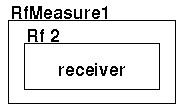
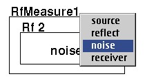
Figure 3: New "Rectangle" Switches in rev B4 and after.
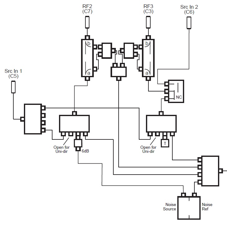
Figure 4: CMC "Octagon" Switches in rev B3 and earlier.
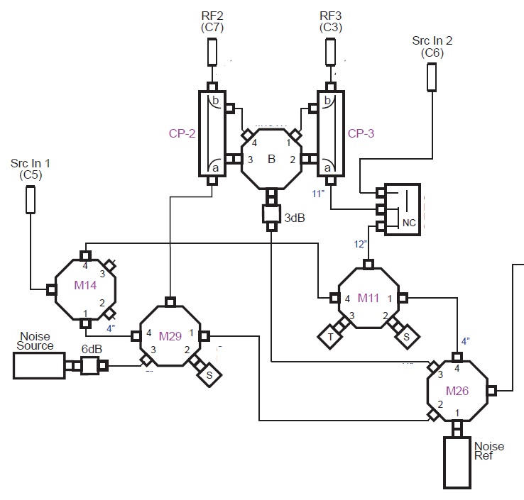
Figure 5: Block Diagram Showing Testplan Change (Signal Terminated at Noise Src vs Open)
Table of RI8567B TIMs
Affected instruments are HW Version "B4" and later.
Switch | HW Ver | Serial Number Ranges | Shipped |
Old | B1 | RIA - RLZ | 2011-05 |
Old | B2 | RMK - RMV | 2012-04 |
Old | B3 | PR0 - RPS | 2013-05 |
New | B4 | RPV - RPX | 2014-05 |
New | B5 | RIR - RR2 | 2014-07 |
New | B6 | RR4 - RR5 | 2014-08 |
New | B7 | RR7 - R2G | 2017-01 |
New | B8 | RVR - RW3 | 2018-06 |
New | B9 | RWF - RWM | 2020-06 |
New | BA | RWN - RXC | 2021-03 |
As of November 2025, rev BA is the latest hardware revision.
TIM Block Diagrams
 RI8567BA_Test_Set_12GHz w Cable Lengths.pdf<-- Switches by New Vendor