
Below are links to the associated procedures and guidelines:
- Safety Information (link)
- Emergency Off Switch/Emergency Shut Down provided by Advantest V93000 or Facility
- Start Up Procedure
- Docking a Fixture or Diagnostic Plate (link)
- Docking to Handler or Prober (link)
- Shut Down Procedure
Start Up Procedure:
- All steps in the To Attach a RI8611A Cassini V93K CTH Infrastructure to Advantest V93000 SoC Tester procedure has been completed.
- Proceed with System Startup with Advantest Software (contact Advantest Support for details). Wait for the rTalk window to show "Tester Loaded" in the message widow before proceeding.
- Latch the Fixture
Note: Fixture should remain unlatched while a Startup is performed to avoid damaging sensitive components on the DIB board. - From the RTalk window, use the cassini > tester browse app and choose check to identify and activate the Fixture and DeviceInterface instruments and cal data.
- (Optional) Dock to Handler/Prober
Standard Shutdown Procedure:
- If attached to a Handler/Prober, unlatch Fixture from Handler/Prober
- Unlatch Fixture from Cassini C93K CTH Infrastructure and store in case
- Follow the Advantest Shutdown Procedure (contact Advantest Support for details)
To Power On the RI8611A Cassini V93K CTH Infrastructure:
- Unlatch and Remove any Fixture or Diag/Cal plate from the RI8611A Cassini V93K CTH Infrastructure.
WARNING: The DUT, DIB or Fixture could be damaged if the Fixture is latched while the system is starting up. Never add or remove TIMs while the Fixture is latched to the test head. - Connect the power to the AC cable to the GST360A48 360W AC-DC Switching Adaptor and USB Type C cable to the system controller.
- (Optional) Switch ON the AC power from the Advantest control or switched power strip.
- Proceed with Advantest V93000 Startup Procedure (contact Advantest Support for details), the rTalk window will appear and "Tester Loaded" message appears when the system is ready.
To Power Off the RI8611A Cassini V93K CTH Infrastructure:
- Unlatch and Remove the Fixture or Diag/Cal plate.
- (Optional) Switch OFF from the Advantest Control or Switched Power strip.
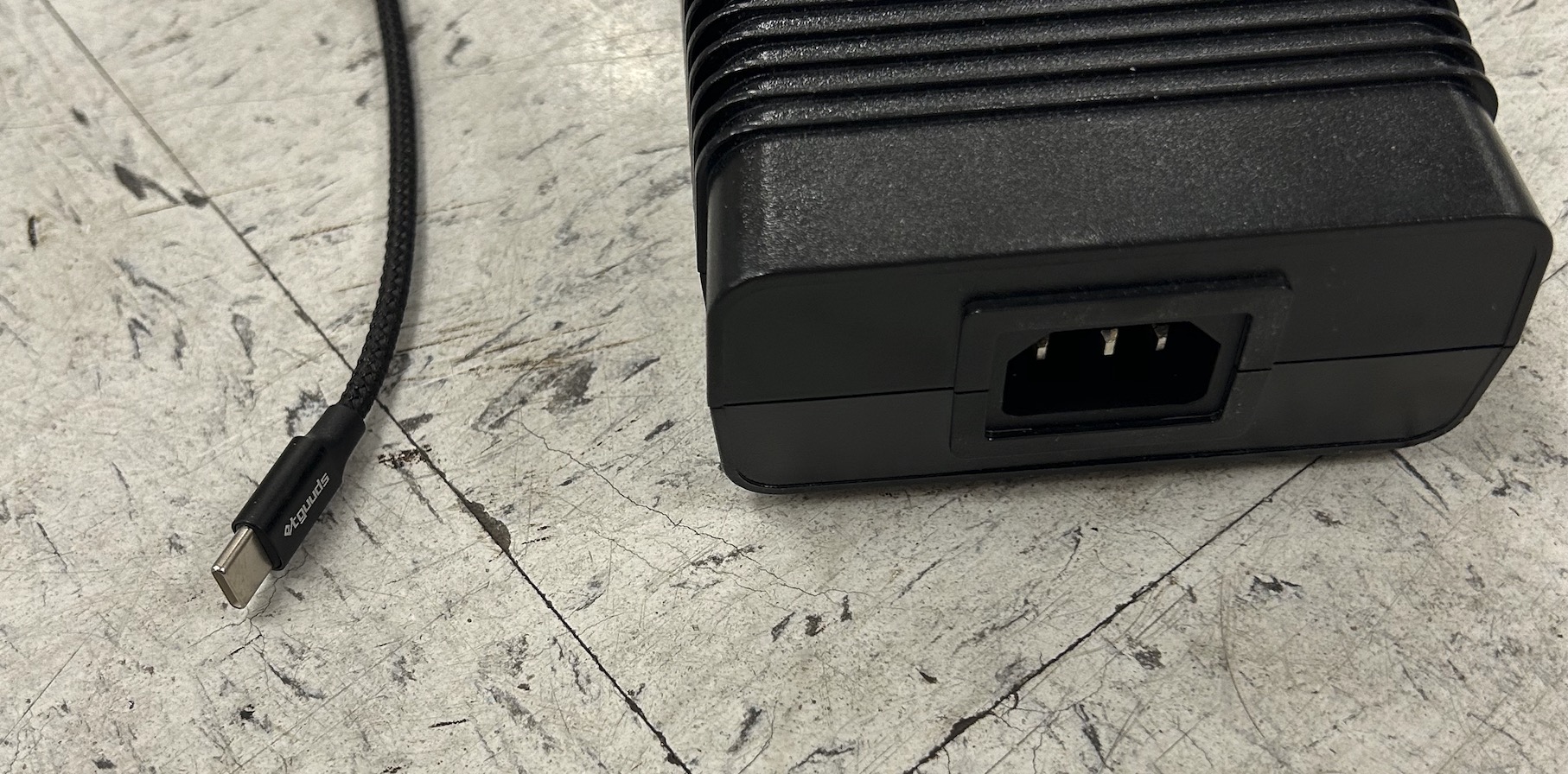
Figure 2: Mechanical Specification of 48V Power Supply
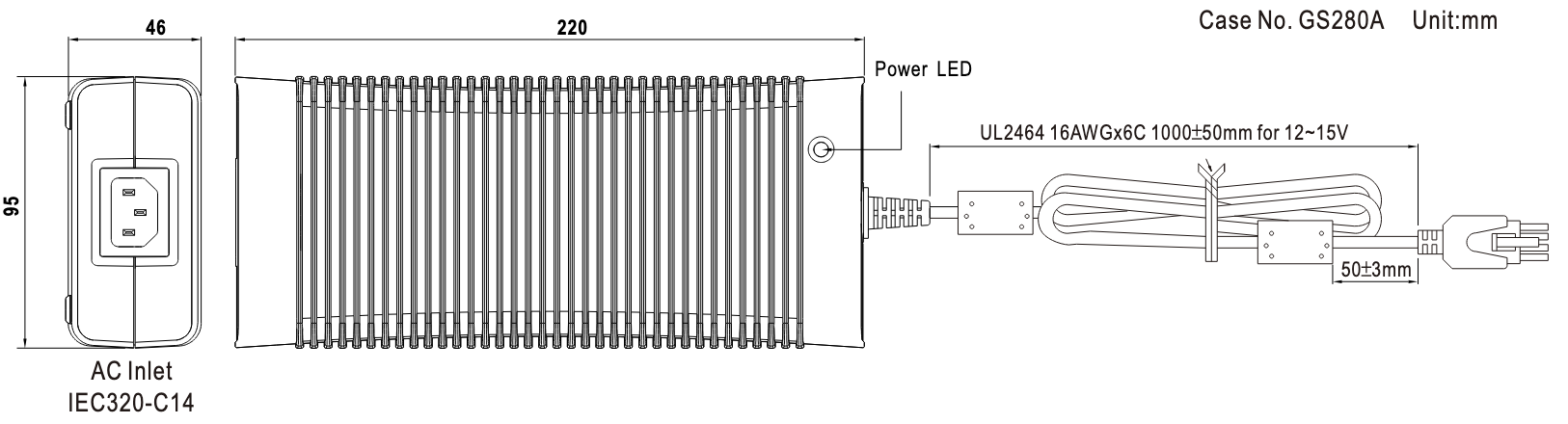
Figure32: AC Plug IEC320-C13 on Advantest V93K with EMO