

This document provides general safety information to prevent injury and outlines hazards for personnel using or near the RI8611A Cassini V93K CTH Infrastructure (referred to as "Cassini Infrastructure") and the MZYB336A Cart for Cassini V93K CTH Infrastructure (referred to as "Cart"). The Cassini Infrastructure and Advantest V93000 systems are conceptually similar to a production Device Handler or Wafer Prober and the ATE System that performs measurements within a test cell. (See Figure 1) These two systems are independent devices with minimal interconnection and can be used separately.
This document outlines the design elements that address the welfare and safety of the user and facility where an RI8611A Cassini V93K CTH Infrastructure is installed, in operation and when being moved or stored on the Cart.
General Safety
Cassini test systems are designed with an emphasis on safety and consider hazards described by the U.S. Department of Labor OSHA1 compliant safety program and conforming to EU safety standards while performing the normal operation of the test system. If the system is used in a manner not specified in the instructions, the protection provided by the equipment may be impaired. The following safety information is based on a standard operating air temperature from 10° to 35°C (50°to 95°F) and humidity from 8% to 80%.
The following symbols are provided with their meanings along with their application to the test system.
EU Declaration of Conformity
The Roos Instruments Cassini 16 system (labeled as "SpyderV93K" below the RI logo on the top cover, shown in Figure 1) meets the essential requirements of both the Electromagnetic Compatibility Directive (EMCD) 2014/30/EU and the Low Voltage Directive (LVD) 2014/35/EU. This compliance is based on the application of the following EU Harmonized Standards:
- EN 61326-1:2013
- EN 61000-3-2:2006 + A1:2009 + A2:2009
- EN 61000-3-3:2013
- EN 61010-1:2011/A1:2020
As a result, the system fully adheres to the relevant provisions of the EMCD and LVD.2
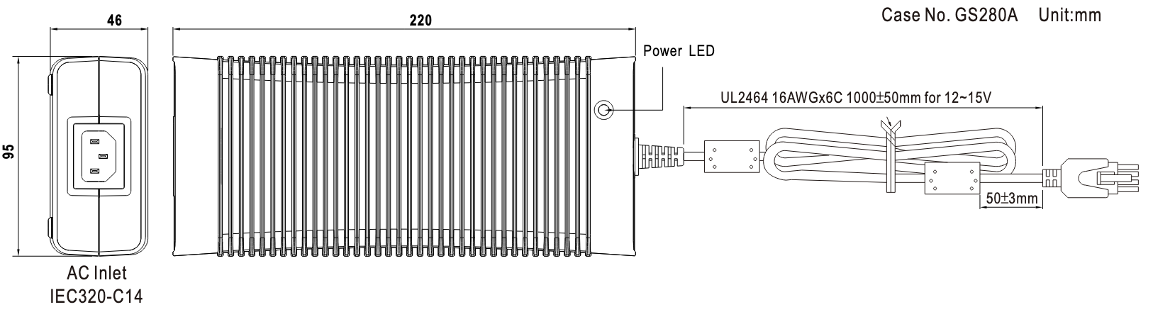
The RI8611A Cassini V93K CTH Infrastructure operates using 48V power supplied by the GST360A48-C6P 360W AC-DC Switching Adaptor from MEAN WELL Enterprises Co., Ltd. (referred to as "AC-DC adapter") as shown in Figure 12. This adaptor is mounted on the Advantest V93000 Testhead and supports switched power and/or single EMO functionality. It connects with the Cassini Infrastructure with a Six-Pin Molex Connector (see Figures 9, 10, and 11) that are connected during original manufacturing from the factory and should only be disconnected for service.
For further details and product specifications, refer to the CE Mark Conformity Declaration for the GST360A48-C6P AC-DC Switching Adaptor for Cassini V93K Infrastructure (https://roos.com/docs/RBEH-DBE2QE).
AC Power Connections
The Roos RI8611A Cassini V93K CTH Infrastructure system operates on low-power 48V DC, supplied by a CE-certified external commercial AC-DC adapter. This adapter connects to an AC mains input of 110–240V AC, with a maximum power rating of 380W. (See Figure 12)
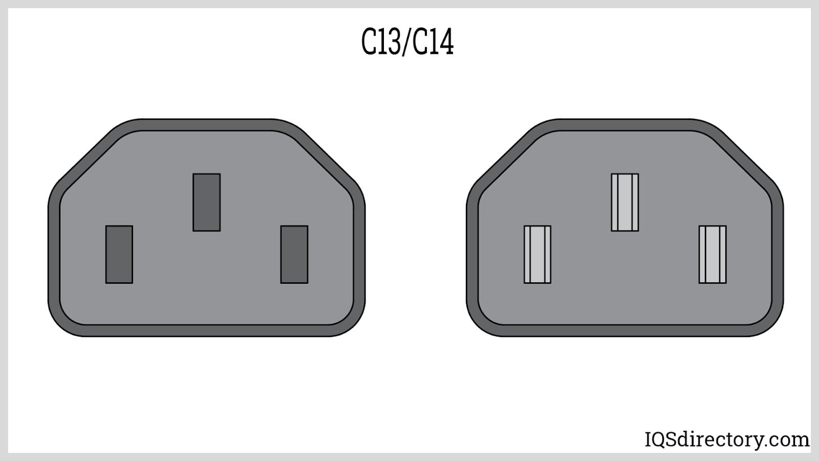
If the built-in power connection is already occupied by another optional V93000 accessory, the customer must provide an alternate connection that still complies with EMO safety standards. One possible solution is to use a CE-certified 1-to-2 IEC320-C14 AC power Y splitter cable. In cases where the Advantest AC power plug is not switchable, it is recommended to install a switchable IEC320-C14 power strip. This allows the power to be turned OFF before connecting or disconnecting the system, ensuring safe operation.
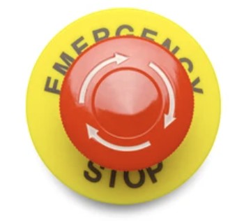
Emergency OFF (EMO)
RI recommends the Cassini AC Power Supply plugged directly into the Advantest V93000 test head AC power connection or other facility provided power so that it takes advantage of the EMO and mains protection and, if available, auxiliary switching capability.
Safety / ESD AntiStatic Ground
For safety, the RI8611A Cassini V93K CTH Infrastructure is properly grounded via its 48V AC-DC adapter. A yellow-green ground wire, mechanically attached to the infrastructure, connects it to earth ground through this adapter.
This ground connection is extended further by a dedicated ground wire integrated into the cable assembly that links the AC adapter to the Advantest V93000 Testhead AC power plug (see Figures 9 and 10).
When the RI8611A is docked to the V93000, both systems become grounded through mechanical clamping at the Fixture/Device Interface Board (DIB) interface (see Figure 8).
While the system is not in use and stored on the cart:
- RI recommends attaching a static control chain (not included) that maintains contact with the floor.
- Although the cart has static-safe casters, it is designed for transport and storage only and does not provide a suitable ESD ground point during operation.
Electrostatic Discharge (ESD) may damage or reduces the life of the test system or its components. The following steps should minimize ESD damage.
CREATE AN ANTISTATIC WORK AREA BY:
• Spraying all surfaces (floors as well as tables) with an antistatic solution.
• Handling all electronic parts and assemblies in antistatic containers.
• Using static conductive floor mats and grounded antistatic service mats.
• Using grounded wrist straps (with 1-Megohm resistors).
• Discharge static from personnel before handling electronic components or printed circuit boards by using wrist ground straps and antistatic outer clothing.
• Discharge static from tools before they are used to service electronic assemblies.
• Service or work on electronic assemblies only in areas which are static-controlled.
• Remove the following materials from the test/work areas:
• Food containers and wrappers (plastic, cellophane, paper and Styrofoam)
• Clothing and shoes fabricated from man-made materials (rubber-soled shoes)
• Paper
• Tapes
• Maintain humidity levels between 40 and 60%.
• In severe static-inducing conditions, for example in automated work areas or where the humidity levels are very low, use air ionizers.
• Consult an ESD Control Specialist for additional recommendations.
Electrical Shock Hazards
There are NO electrical shock hazards from any of the exposed electrical connections on the test head or on any surface of the system. The system uses 48 volts or less and shock hazards are typically designated as to 50 volts or higher 3. No high-voltage cables or connections are exposed at any time during operations or when moving the system. Fixtures and Tester Instrument Modules (TIMs) can be safely removed "hot" without disconnecting power without damaging the equipment or exposing live connections to the operator. The system utilizes an external Emergency Off (EMO) button that instantly disables AC power to the 48V AC-DC Adapter.
IMPORTANT EXCEPTION: RI8589 High Power TIM can pulse up to 220V for a short time, exposing a burn risk to fingers if they touch the active terminal while Diagnostic or Calibration testplans are run. Consult the Tester Configuration to understand if this instrument is included in the configuration.
Dimensional Weight Hazard
The RI8611A Cassini V93K CTH Infrastructure weighs 18 kg and includes four handles for lifting. While this weight is within the safe limit for a single-person lift, RI recommends a two-person lift due to the unit’s physical dimensions. (See Figure 4)
⚠️ Exercise caution when unpacking, installing, or removing the RI8611A. Always unlatch and remove all Test Instrument Modules (TIMs) and Fixtures before lifting the Infrastructure.
The Cassini system without the Fixture and Device Interface Board weighs approximately 34 kg.
A fully loaded system, including the Infrastructure, TIMs, Fixture, and Device Interface, weighs around 42 kg, which remains well within the 75 kg maximum DIB weight limit for the V93000.
When not in use, place the RI8611A Cassini Infrastructure on the MZYB336A Cart to simplify storage and ensure safe handling. (See Figure 1)
Note: RI and Advantest have performed center-of-gravity and tipping stability calculations using the standard Advantest-recommended manipulators. If alternative manipulators are employed, the customer is responsible for conducting a mechanical safety analysis to ensure compliance.
Unpack and Setup Hazards
Refer to the procedures outlined in the Cassini V93K CTH Infrastructure Attach and Remove with Cart document to ensure safe installation of the Infrastructure.
The RI8611A Cassini V93K CTH Infrastructure is designed for use with the Advantest V93000 SoC Tester (see Figure 2). During operation, the RI8611A is manually docked to the V93000 using the same method applied to standard Advantest Load Board or Probe Card Assemblies (see Figure 3 and 8).
For storage and mobility, the MZYB336A Cart includes ESD-safe lockable casters and dual push bars, allowing easy handling (see Figure 1). A latching lock secures the Infrastructure during storage.
Figure 3 also shows the RI8611A being removed from the cart in preparation for installation on the V93000.
Pinch Point Hazards
Always use caution when docking the Handler or Prober to the Fixture and Fixture to the Test Head. Use handles when available and use caution when latching and unlatching the Fixture or Diag/Cal Interface Plate. Do NOT insert fingers under the Fixture pull down latches at any time.
Ergonomic Hazards
Repetitive stress injuries created by ergonomic workstation hazards are not of concern with normal system operations. Operators are NOT expected to use the touch screen or mouse and keyboard for an extended period of time (more than an hour). Most operators only use the system for minutes at a time, below industry guidelines for workstation safety4. If the system is primarily used for test plan development, however, extended periods of work may occur. A chair or stool with proper height adjustment and back support or a padded mat for standing support is suggested if the person remains in position for more than 60 minutes with 5 to 10-minute breaks.
Fire and Chemical Safety Hazards
There are NO explosive or combustible materials in the system. No chemical safety guidelines are required because no hazardous chemicals are used in the operation of the system. Exposure to hazardous amounts of lead is not possible due to the lack of direct contact to components that may have been soldered with lead. As a precaution, DO NOT EAT, DRINK, OR SMOKE after handling damaged internal electronic components until you have washed your hands.
RoHS Exemption
Roos Instruments equipment is exempt from RoHS standards for lead free components due to the performance characteristics of lead free components and the class of hardware5 (Large-scale stationary industrial tools (LSSIT)).
Safety Precautions
Users should always adhere to the safety guidelines provided below:
- Read all of these instructions.
- Save this manual for later use.
- Do not use this test system unless it has been installed and maintained as specified in the appropriate Site Preparation and Installation and Maintenance documents.
- Shut off all power before cleaning or servicing the test system. Shut down and remove test instrument modules, fixtures, and/or auxiliary equipment from the system before moving, cleaning or servicing.
- Do not drop any part of the test system.
- Do not obstruct or cover the slots and openings in the system controller, test instrument modules, or test system. These openings provide cooling and ventilation for the computer and test equipment.
- Do not stack anything on top of the test system or auxiliary racks with the except of workstation equipment: monitors, keyboard, mouse.
- Do not place anything next to the test system that can block or impede proper airflow to or from the test system.
- Operate the test system only from the type of power source indicated on the labels and in the manuals.
- Keep power cords away from areas where people stand or walk. Avoid stepping on power cables.
- Follow all warnings and instructions marked on the labels.
- Never spill liquids of any kind on the system controller, test system, test instrument modules, fixtures or related equipment.
- Do not attempt to service the system controller, the computer peripherals, or the test system without consulting a Roos Instrument’s service or support engineer. See the maintenance manuals for servicing procedures before opening any of equipment on the test system. Repair and maintenance should be done only by qualified service or repair persons.
- Shut off the entire test system under any of the following conditions:
- Smoke or an odor is present.
- Any of the infrastructure cooling fans fail to operate.
- Any kind of liquid has been spilled on any part of the system controller, computer peripheral, or test system.
- The system controller, computer peripheral or any part of the test system has been dropped.
- The system controller, the computer peripherals, or any part of the infrastructure has been damaged.
- Contact Roos Instruments support for service or repair under any of the following conditions:
- The controller, computer peripherals, or test system show any change in performance.
- Test programs does not run properly.
- The test head or any part of the test system cannot be adjusted for a test program.
Figure 1: RI8611A Cassini V93K CTH Infrastructure installed on an Advantest V93000 CTH
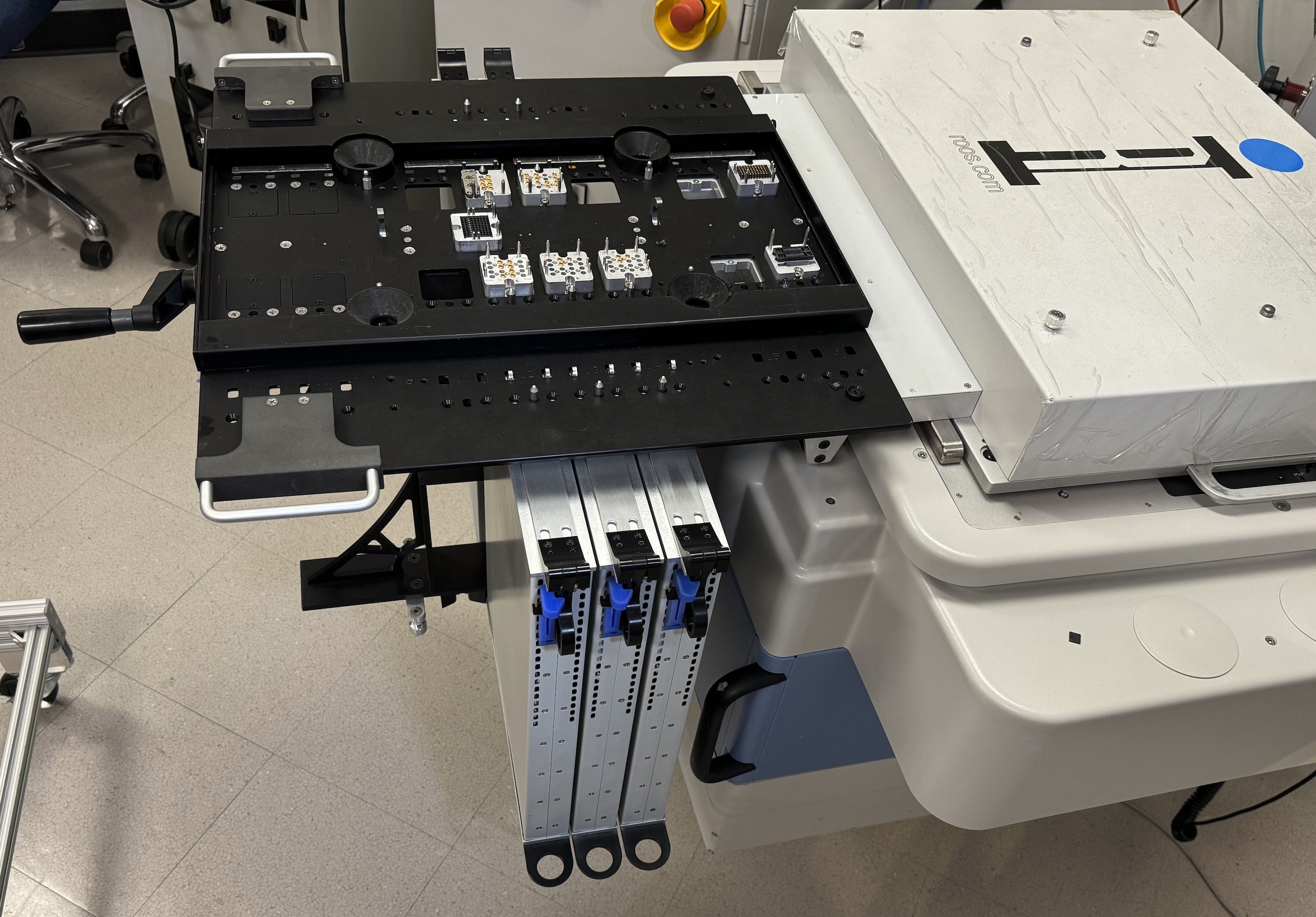
Figure 2: RI8611A Cassini V93K CTH Infrastructure hardware with TIMs and Test Fixture on Cart (P/N MZYB336A)
Figure 3: Align and Attach Cassini V93K CTH Infrastructure
Figure 4: Two Person Lift with Handles
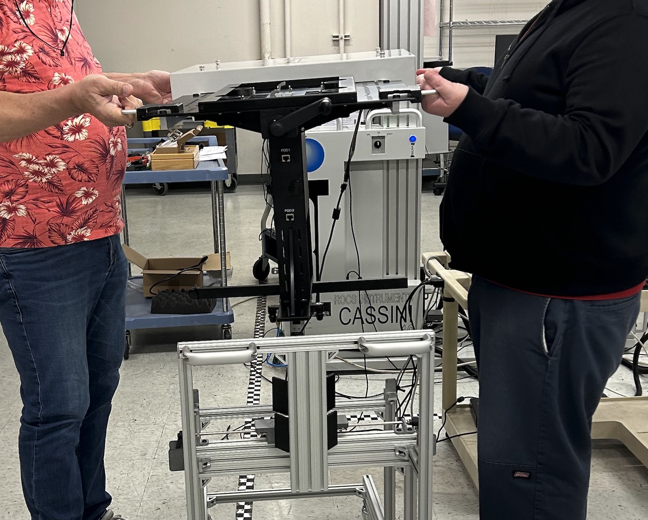
Figure 5: USB and AC Plugs
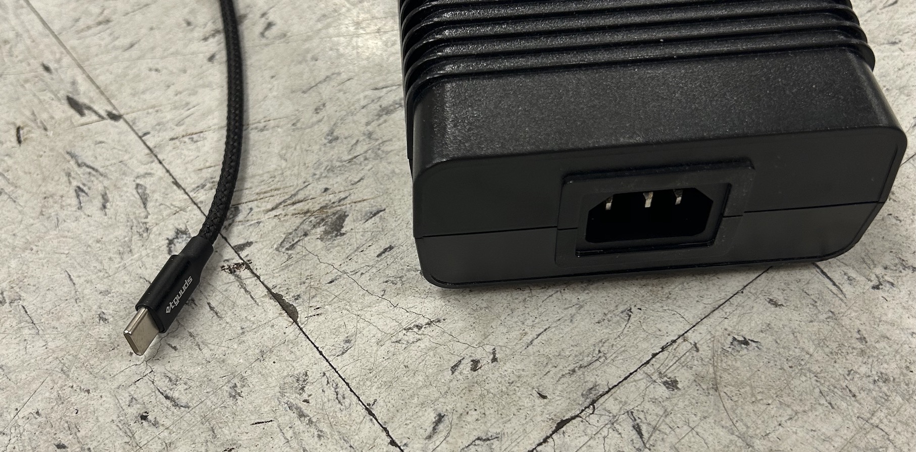
Figure 6: AC Plug on Advantest V93K with EMO
Figure 7: AC Y Splitter and C13 AC Switch
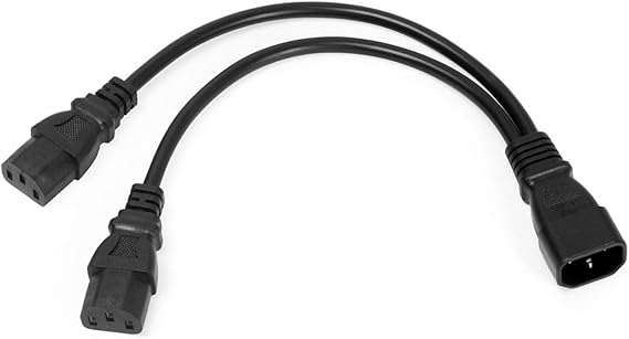
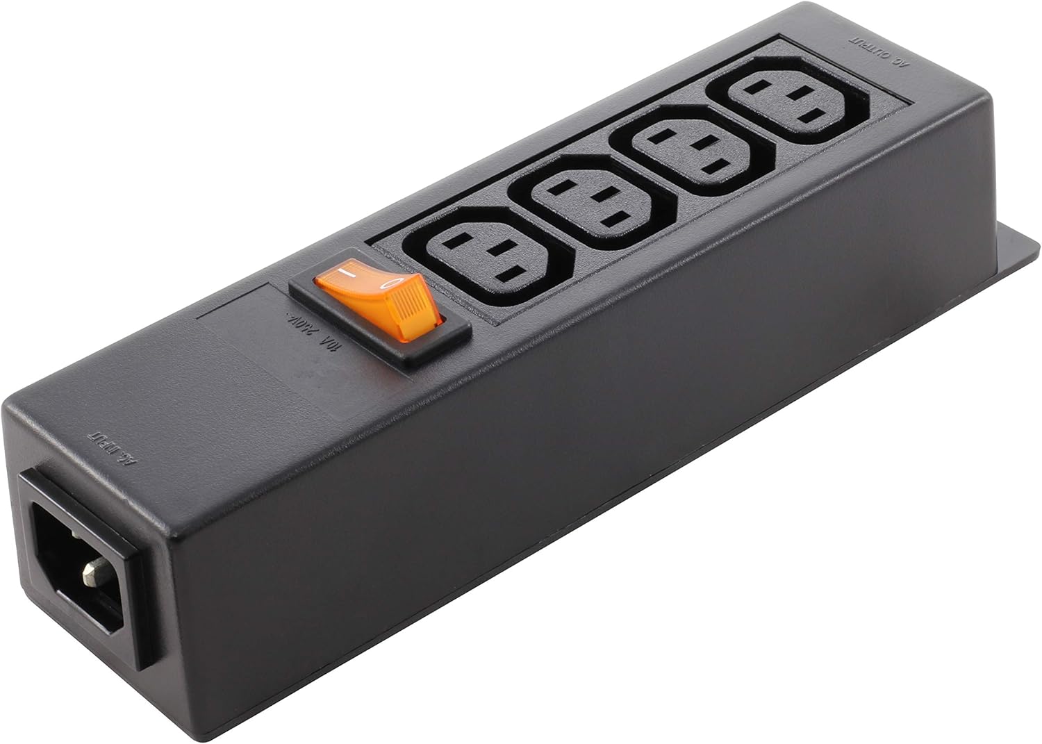
Figure 8: V93K DIB Interface Mechanical Clamp (Cover Removed)
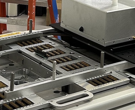
Figure 9: 48V DC 25A Power Plug with Grounding Cable (remains connected)
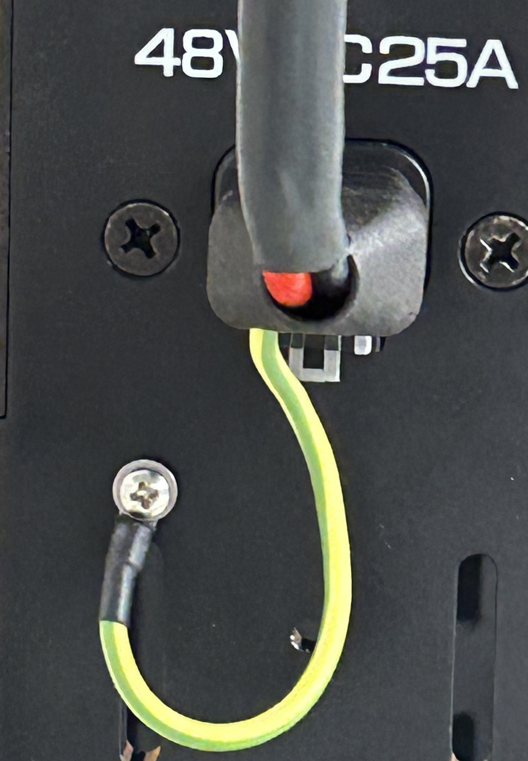
Figure 10: DC Connector to 360W AC-DC Adaptor
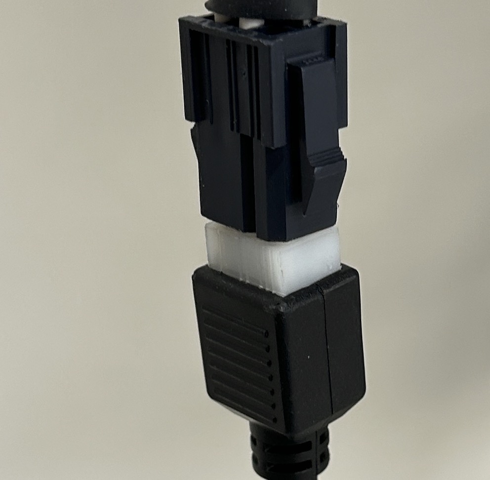
Figure 11: Six-Pin Molex Connector Diagram and Pinout
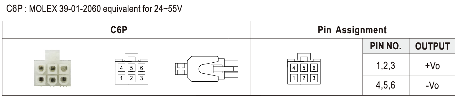
Figure 12: Mechanical Specification of 48V Power Supply
Footnotes:
1 - U.S. Department of Labor, Occupational Safety & Health Administration, http://www.osha.gov/
2 - CE Declaration of Conformity for Cassini 16 Document No. 2025. CE Mark Conformity - Cassini 16 https://roos.com/docs/RBEH-8HWR6M
3 - Encyclopedia of occupational health, Jeanne Mager Stellman, pg. 52-5
4 - Handbook of OSHA constructions safety and health, Charles D. Reese, pg 218
5 - ✔ RoHS Product Categories & Exemptions https://www.rohsguide.com/rohs-categories.htm
- Answer_Test_and_Measurement_Coalition.pdf https://rohs.biois.eu/Answer_Test_and_Measurement_Coalition.pdf )